3. The
Baxandall Class-D Oscillator with a Pulse-Width Modulated Voltage Drive
It is more
interesting to used pulse width modulation to generate a more or less crude
approximation to the raised half-sine wave at the free end of L3 to create the
same effect.
Because the
PWM waveform can’t rise above the power supply rail, we lose a third of our
output amplitude, but that can be dealt with in the output windings (L4 and
L5).
We have the
same problem with the uncertainty in the resonant frequency of the tank
circuit, but in this case we can use a phase-locked loop to force a voltage
controlled oscillator to run at some convenient multiple (at least twelve
times) of the resonant frequency – the CMOS 4046 or one of its variants could
be used to do the job.
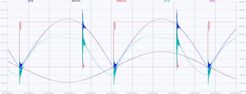
The circuit
simulated doesn’t include the 4046, and was tuned by adjusting the period of V2
by hand to 5.32usec, longer than the 5.236usec
that one would expect from the resonant frequency of the tank circuit
(L1 plus L2 in parallel with C1).
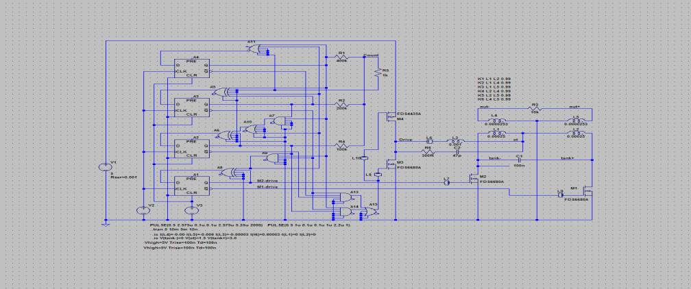
Even with
the snubber in parallel with L3 and L6, there is very nasty 10MHz ringing on
the switcher-overs between M3 and M4 – non-over-lapping drive waveforms would
help.
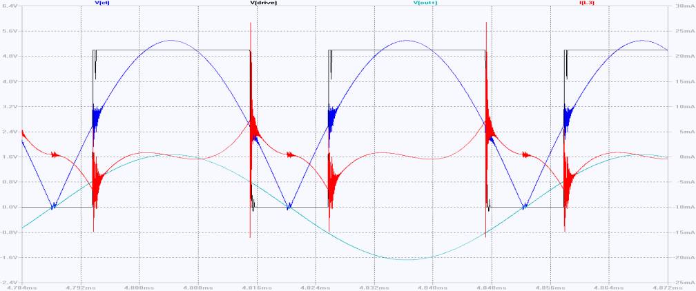
The current
swing in the inductor L3 is now +/-7mA (ignoring the switching spikes to +25mA
and –15mA).
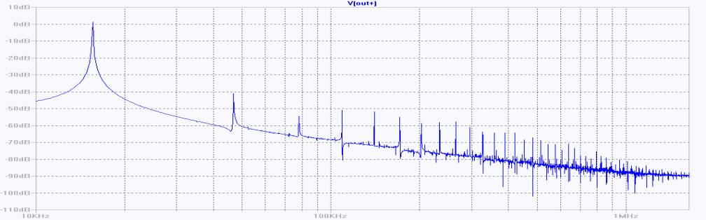
This gives
the third harmonic distortion some 48dB below the fundamental – not as good as
the resonant trap at 55dB down, but better than the classic circuit at 40dB.
The circuit
still looks good with a 100R at R3, rather than the 10k used above
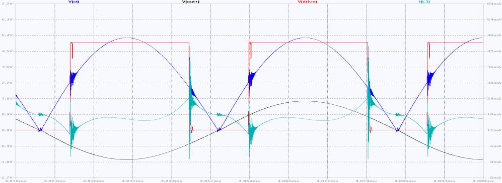
though the
third harmonic is a lot higher, only 37dB below the fundamental.
Shifting
the phase of the drive waveform to bring the drive current more or less
in-phase with the output voltage
doesn’t
make much difference to the distortion, though the frequency moves a bit
higher.
Interestingly,
the voltage at the centre tap moves from peaking about 1% too early to peaking
about 2.5% too late (15.9usec to 16.3usec).
Obviously
I’d like to try a slightly smaller phase advance to get the drive current
(though L3) a little more nearly in-phase with the voltage across the tank
circuit (essentially Vct), but that would involve a much longer counter which
would be difficult to manage in LTSpice.
In real
life, a longer counter wouldn’t be a problem.